

An HVACR system with an expansion valve (TXV) must be charged by Sub-Cooling. A system with a fixed metering device must be charged by Superheat.
What is Superheat?
Take me to start calculating Superheat
Take me to start calculating Sub-Cooling
Take me to Refrigerant Troubleshooting
Unitary (refrigerant-containing) systems using capillary tube or a fixed orifice/actuator piston as refrigerant metering devices should be charged by the evaporative Superheat method. Saturation temperature or boiling temperature is the temperature at which fluid changes from a vapor to a liquid or from a liquid to a vapor. When the condensed-liquid refrigerant enters the evaporator is is metered and goes from a high-pressure liquid to a low-pressure liquid. With proper air flow across the evaporator coil heat is absorbed and is transferred to the refrigerant. This sensible heat added to the low-pressure, liquid refrigerant will turn it into a low-pressure vapor. The additional temperature (sensible and latent heat) that is added during this conversion is called Superheat. In a proper operation, the refrigerant is in its most vaporous form leaving the evaporator. Increasing the fluid's pressure will raise the refrigerant's temperature and decreasing the pressure will lower its temperature.
Units to be charged by using the Superheat method should provide a charging chart inside the condenser's (outdoor unit) service panel. Sometimes these charts are available from the unit's wholesale distributor, manufacturer's web site or installation/service manuals. Most of the time they are glued inside the condenser's service panel. The charts may require an indoor wet bulb temperature reading as well as an outdoor dry bulb temperature reading.
The indoor wet bulb reading indicates the total heat of the air and the total load on the indoor coil (sensible heat plus latent heat).
The dry bulb temperature will only determine outdoor sensible heat. Think of it as boiling water. The water temperature of 212°F (100°C) is the sensible heat. The heat that causes a change of state (water to vapor) with no change in temperature is called latent heat. Latent heat does not affect the temperature. The sum of the sensible and latent heat of the air is called enthalpy or total heat. In determining a Target Superheat cross referencing the indoor wet bulb and outdoor dry bulb temperatures, the charging chart will recommend the proper Target Superheat for that system.
There are two effect methods of determining a proper Superheat refrigerant charge for an HVACR system: Evaporative Superheat and Target Superheat. The tools you will need to determine Evaporative Superheat and Target Superheat, will be a dry-bulb temperature device: probe or clamp-on, a web-bulb temperature device: sling psychrometer or digital, and a set of compound and high-pressure manifold gauges.

The Evaporator Superheat Method should be the first effective method of properly charging a capillary tube or a fixed orifice/actuator piston as refrigerant metering device. Install your pressure gauges to the outdoor condensing unit. In the air conditioning mode this would be the compound, low-pressure gauge to the suction (vapor) refrigerant line at its service valve. The high-pressure gauge is connected to the liquid line also at its service valve. On most residential systems, the service valves are fully open (back seated). In commercial systems, the valves may need to be mid-seated to be able to obtain refrigerant pressures. Remember to reseat the valves before removing your gauges!

SUPERHEAT METHOD
Evaporator Superheat Method:
1. Take the suction line pressure and temperature at the condenser's suction service valve (air conditioning) or service port at the compressor (heat pump). If you use a probe-type thermometer, put a piece of pipe insulation around the probe and pipe.

2. Convert saturation pressure=temperature with a Pressure-Temperature chart (Go to PT Chart).Not all evaporators have a suction service port, you can still take the pressure at the condenser's service port in air conditioning mode. If a reading is obtained at the condenser on a heat pump, use the common suction pressure port because there is a pressure drop through the reversing valve. If the suction line is longer than 25' you may have to add a few pounds of pressure in your pressure-to-temperature conversion due to pressure drop in the suction line.
3. Subtract one from the other (Suction Line Temp - Saturation Temp). The difference is the amount the refrigerant gas has heated above saturated temperature (Superheat).
Basic Rule for Evaporative Superheat
A. When ambient (outside) air entering condenser is 65°F - 85°F, the Superheat should roughly be 12° - 15°.
B. If the ambient air temperature is over 85°F the Superheat should roughly be 8° - 12°.
C. If Superheat is low then refrigerant is flooding the Evaporator. Do not adjust the refrigerant charge until a troubleshooting diagnosis has been established.
D. If Superheat is high then the Evaporator is starving for refrigerant. Do not adjust the refrigerant charge until a troubleshooting diagnosis has been established.
E. Remember the amount of air traveling through the Evaporator also determines the amount of Superheat.
TECH NOTE: If the Superheat is correct and the suction pressure is low, the system probably has low airflow. Correct the airflow problem and check the charge again.
Use bottom scroll or swipe left to view the whole chart on smaller screens.
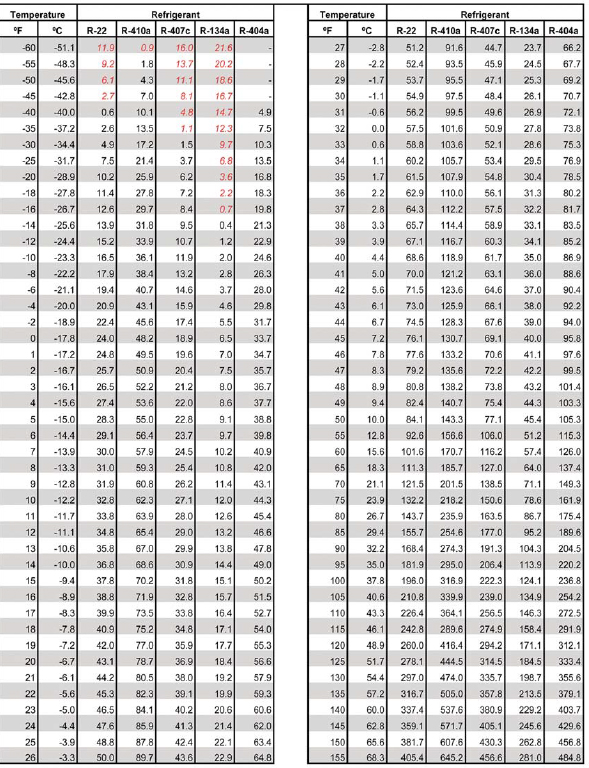
Pressure Temperature Chart. Find the correct refrigerant.
Intersect the actual pressure (psig) to obtain the refrigerant's temperature.

Targeted Superheat Method:
This method, like the Evaporator Superheat Method, is most effective when the indoor conditions are within desired indoor comfort conditions or as a secondary method.
1. Take a dry bulb temperature of the outdoor ambient air entering the condenser coil.
2.Take the suction line pressure and temperature at the condenser's suction service valve (air conditioning) or service port at the compressor (heat pump). If you use a probe-type thermometer, put a piece of pipe insulation around the probe and suction pipe.
3. Using Table 2, Intersect the reading of the vapor pressure and outdoor dry-bulb temperature to obtain the vapor line temperature.
Use bottom scroll or swipe left to view the whole chart on smaller screens.
| Table 2 | VAPOR PRESSURE AT SERVICE VALVE | ||||||||||||||||||
|---|---|---|---|---|---|---|---|---|---|---|---|---|---|---|---|---|---|---|---|
| 52 | 54 | 56 | 58 | 60 | 62 | 64 | 66 | 68 | 70 | 72 | 74 | 76 | 78 | 80 | 82 | 84 | 86 | ||
| OD DB (F°) | VAPOR LINE TEMPERATURE (F°) | ||||||||||||||||||
| 101 + | 43 | 45 | 46 | 47 | 49 | 50 | 51 | 53 | 54 | 55 | |||||||||
| 100 | 44 | 45 | 47 | 48 | 49 | 51 | 52 | 53 | 55 | 56 | 57 | ||||||||
| 95 | 45 | 47 | 48 | 50 | 51 | 52 | 54 | 55 | 56 | 58 | 59 | 60 | |||||||
| 90 | 49 | 51 | 52 | 54 | 55 | 56 | 58 | 59 | 60 | 62 | |||||||||
| 85 | 52 | 53 | 55 | 56 | 58 | 59 | 61 | 62 | 63 | ||||||||||
| 80 | 53 | 55 | 56 | 58 | 59 | 61 | 62 | 63 | 65 | ||||||||||
| 75 | 55 | 56 | 58 | 59 | 61 | 62 | 64 | 65 | 66 | ||||||||||
| 70 | 55 | 57 | 58 | 60 | 61 | 63 | 64 | 66 | 67 | ||||||||||
| 65 | 57 | 58 | 60 | 61 | 63 | 64 | 66 | 67 | 69 | ||||||||||
4. If the vapor line temperature is not the same, adjust the refrigerant charge. Adding refrigerant will raise the suction pressure and raise the suction line temperature. Recovering refrigerant will lower the suction pressure and lower the suction line temperature.
TECH NOTE: If your actual Superheat is greater than your targeted Superheat, add refrigerant. If your actual Superheat is lower than your targeted Superheat, recover refrigerant until a proper Superheat measurement is obtained.
Always consider the manufacturer's recommendations and charging charts first when choosing to use either method.

SUB-COOLING METHOD
A thermostatic expansion valve (TXV) is a metering device that controls the amount of refrigerant that enters the evaporator coil.
This process causes the refrigerant to go from a liquid to a vapor. A TXV works by an internal spring, valve pin, and a diaphragm that opens and closes through a thermostatic bulb and refrigerant pressures. The bulb and the capillary tube connected to it has a charge that expands or contracts on temperature change. When the charge expands, this exerts pressure on the diaphragm that opens the valve pin allowing more refrigerant to enter the coil.
The valve pin is surrounded by a spring that puts pressure on the opposite side of the diaphragm to close the valve pin when the bulb's charge contracts, or refrigerant pressures drop. This spring tension is adjustable. Turning the spring's adjustment stem clockwise increases Superheat. Counterclockwise decreases Superheat.
TECH NOTE: Most TXVs are factory set and should never be manually adjusted. In most cases, Superheat and Sub-Cooling can be adjusted with the addition or removal of the refrigerant charge.

Condenser Sub-Cooling Method:
Sub-Cooling is the amount of liquid held back in the condenser. This allows the liquid to expel heat below saturation pressure=temperature. For every 1° of Sub-Cooling at the same condensing pressure, capacity will increase 0.5%. Increasing Sub-Cooling with an increase of discharge pressure and compression ratio decreases capacity. Add 5° of Sub-Cooling for every 30 ft of liquid line lift. Liquid Sub-Cooling is normally measured at the liquid line service valve. It's usually between 12°F and 15°F.
Always use manufacturer's recommendations first before using a standard Sub-Cooling chart.
1. On the condenser, take a pressure reading at the liquid line service port. The refrigerant saturation pressure=temperature is when the refrigerant is turning from a vapor to a liquid. At saturation pressure=temperature, both high-pressure liquid and vapor are at the same temperature.
2. Use a temperature-to-pressure chart to convert the pressure to the saturated condensing temperature of the refrigerant (Go to PT Chart).
3. Attach a thermometer to the liquid line. If you use a probe-type thermometer, put a piece of pipe insulation around the probe and pipe. The temperature that you read with the thermometer should be lower than the saturated condensing temperature. The difference between the liquid line temperature and the saturated condensing temperature is Sub-Cooling.
Sub-Cooling Calculation Check:
Using Table 3 below, you can check the range of Sub-Cooling by taking a wet bulb reading at the evaporator and a dry bulb reading from the air entering the condenser. This check will determine if your Sub-Cooling calculation falls within a proper range. This chart should only be used if the manufacturer's recommendations are not available.
Use bottom scroll or swipe left to view the whole chart on smaller screens.
| Table 3 | EVAPORATOR SUCTION LINE TEMPERATURE - WB (F°) | |||||||||
|---|---|---|---|---|---|---|---|---|---|---|
| 57 | 59 | 61 | 63 | 65 | 67 | 69 | 71 | 73 | ||
| OD - DB (F°) | Sub-Cooling | |||||||||
| 115 | 15 | 14 | 13 | 12 | 10 | 8 | 6 | 4 | 2 | |
| 110 | 17 | 16 | 15 | 13 | 12 | 10 | 8 | 6 | 4 | |
| 105 | 19 | 18 | 17 | 16 | 14 | 12 | 10 | 8 | 6 | |
| 100 | 20 | 19 | 18 | 17 | 15 | 13 | 12 | 10 | 8 | |
| 95 | 21 | 20 | 19 | 18 | 17 | 15 | 13 | 12 | 10 | |
| 90 | 22 | 21 | 20 | 19 | 18 | 16 | 15 | 14 | 12 | |
| 85 | 23 | 22 | 21 | 20 | 19 | 18 | 17 | 16 | 14 | |
| 80 | 24 | 23 | 22 | 21 | 20 | 19 | 18 | 17 | 15 | |
| 75 | 25 | 24 | 23 | 22 | 21 | 20 | 19 | 18 | 17 | |

Add refrigerant to increase Sub-Cooling. Recover refrigerant to reduce Sub-Cooling. Allow +- 2°F tolerance.
TECH NOTE: When using the Condenser Sub-Cooling Method, you can check the suction Superheat to help troubleshoot the TXV. If the expansion valve goes bad, you will have a very low suction Superheat with proper Sub-Cooling. If you get zero degrees Superheat with a TXV, then the TXV is defective and will need to be replaced. A TXV is designed to maintain a constant Superheat. Overcharging a TXV will raise Sub-Cooling, increasing pressures, and decreasing efficiency. Undercharging a TXV will decrease Sub-Cooling, increase Superheat, decreasing capacity, and leave oil in the evaporator.

Refrigerant Superheat and Sub-Cooling Troubleshooting
If the Superheat is high and the Sub-Cooling is low:
The system is undercharged.
If the Superheat is low and the Sub-Cooling is high:
The system is overcharged.
If the Superheat is high and the Sub-Cooling is high:
The system has a refrigerant blockage.
If the Superheat is low and the Sub-Cooling is low:
The system is not metering the refrigerant.
Evaporator = Superheat:
Low Superheat = Too much Refrigerant is going through the Evaporator.
High Superheat = Not Enough Refrigerant is going through the Evaporator.
Condenser = Sub-Cooling:
Low Sub-Cooling = Not Enough Refrigerant is going through the Condenser.
High Sub-Cooling = Too much Refrigerant is going through the Condenser.